-40%
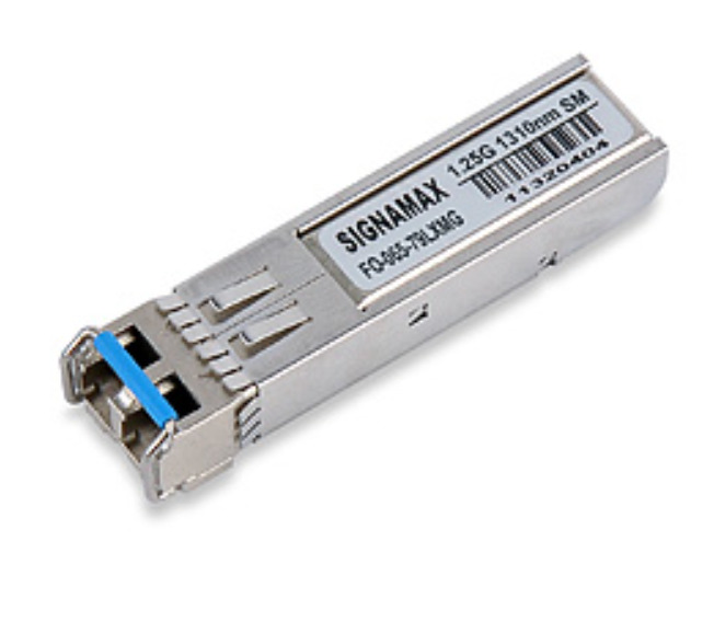
Signamax FO-065-79LXMG 1000BaseLX SFP Fiber interface 1310 nm SM/LC 10 km
$ 78.67
- Description
- Size Guide
Description
065-79LXMG Small Form-factor Pluggable (SFP) Gigabit Interface ModuleThe Signamax 065-79LXMG is a Small Form-factor Pluggable (SFP) singlemode fiber module that supports
Gigabit Ethernet over singlemode fiber cable at distances up to 10 kilometers. It adheres to the IEEE 802.3z
standard for Gigabit Ethernet over singlemode fiber at 1310 nm, and is a cost-effective method of providing
changeable Gigabit Ethernet singlemode interfaces to switches and media converters equipped with a standard
SFP slot.
Applications
• Router / Server interface
• Distributed multi-processing
• Switch to switch interface
• High speed I/O for file server
Key Features
• Compliant with SFP MultiSource Agreement. Compliant with IEEE802.3Z
• SCA-2 Host connector
• Duplex LC connector
• 1310 nm FP Laser
• 3.3V power supply
• Hot-Pluggable capability
• Extended EMI & ESD protection
• Class 1 laser product complies with EN 60825-1
Ordering Information
Part Number Description
065-79LXMG 1000BaseLX SFP Module – SM/LC, 10 km
Summary Specification
PART NUMBER Model /
Spectrum
Light
Source
Link
Power
Budget
Typical Max.
Distance**
Supply
Voltage
Operating
Temp.
065-79LXMG LX
1310 nm
FP Laser 11 dBm 10 km 3.3V 0 ~ 70 °C
** Maximum distances attainable on singlemode fiber circuits are dependent upon a circuit’s conditions; i.e., the number of
splices and patch panels and the number of bends in the circuit path. For comparison with competing products, please use the
Link Power Budget for meaningful comparisons.
`
Network Connectivity Systems
www.signamax.com
999 N.W. 195th Drive • Miami, FL 33169 • 800.446.2377 • 305.944.7710 • Fax: 305.949.4483
Copyright 2013 Signamax, Inc./AESP, Inc. All rights reserved • Signamax Connectivity Systems is a trademark of AESP, Inc. • Specifications subject to change.
065-79LXMG 02212013
DETAILED SPECIFICATIONS
• APPLICABLE STANDARDS
IEEE 802.3z (1000BaseLX Gigabit Ethernet)
• ABSOLUTE MAXIMUM RATINGS
Storage Temperature: TS −40 -- 85 °C
Supply Voltage: Vcc -0.5 -- 6.0 V
Input Voltage: VIN -0.5 --Vcc V
Operating Humidity: 5-95 %
• RECOMMENDED OPERATING CONDITIONS
PARAMETER SYMBOL MIN MAX UNITS NOTE
Ambient Operating
Temperature TAMB 0 70 °C
Supply Voltage Vcc 3.1 5.25 V
Supply Current (3.3V) ITX + IRX 85 mA
• TRANSMITTER ELECTRO-OPTICAL CHARACTERISTICS
Vcc = 3.1 V to 3.5V, TA = 0 °C to 70 °C
PARAMETER SYMBOL MIN TYP. MAX UNITS NOTE
Output Optical Power 9/125 µm
fiber Pout -9 -3 dBm Average
Extinction Ratio ER 9 dB
Center Wavelength λC 1280 1310 1355 nm
Spectral Width (20dB) ∆λ 4 nm
Rise/Fall Time, (20−80%) Tr, f 260 ps
Relative Intensity Noise RIN −120 dB/Hz
Total Jitter TJ 227 ps
Output Eye Compliant with IEEE802.3z
Differential Data Input Swing VIN 200 1660 mV
Transmit Fault Output-Low TX_FAULT 0.0 0.5 V
Transmit Fault Output-High TX_FAULT 2.0 VCC V
• RECEIVER ELECTRO-OPTICAL CHARACTERISTICS
Vcc = 3.1 V to 3.5 V, TA = 0 °C to 70 °C
PARAMETER SYMBOL MIN TYP. MAX UNITS NOTE
Optical Input Power-maximum PIN -3 dBm BER < 10−12
Optical Input Power-minimum
(Sensitivity) PIN -24 -20 dBm BER < 10−12
Operating Center Wavelength λC 1260 1610 nm
Receiver Electrical 3dB Upper
Cutoff Frequency 1500 MHz
Loss of signal –Asserted PA −35 dBm
Loss of signal –Deasserted PD −20 dBm
Differential Data Output Swing Vout 370 2000 MV
Receiver Loss of Signal Output
Voltage-Low RX_LOS 0 0.5 V
Receiver Loss of Signal Output
Voltage-High RX_LOS 2.0 VCC V
Network Connectivity Systems
www.signamax.com
999 N.W. 195th Drive • Miami, FL 33169 • 800.446.2377 • 305.944.7710 • Fax: 305.949.4483
Copyright 2013 Signamax, Inc./AESP, Inc. All rights reserved • Signamax Connectivity Systems is a trademark of AESP, Inc. • Specifications subject to change.
065-79LXMG 02212013
DETAILED SPECIFICATIONS (continued)
• TIMING REQUIREMENTS
Vcc = 3.1 V to 3.5V, TA = 0 °C to 70 °C
PARAMETER SYMBOL MIN TYP. MAX UNITS NOTE
TX_DISABLE Assert Time t_off 10 µs
TX_DISABLE Negate Time t_on 1 ms
Time to initialize, include reset
of TX_FAULT t_init 300 ms
TX_FAULT from fault to
assertion t_fault 100 µs
TX_DISABLE time to start
reset t_reset 10 µs
Receiver Loss of Signal Assert
Time (off to on) tA,RX_LOS 100 µs
Receiver Loss of Signal Assert
Time (on to off) tD,RX_LOS 100 µs
• DIMENSIONS (mm)
• REGULATORY COMPLIANCE
Feature Test Method Performance
Electrostatic Discharge
(ESD) to optical
connector
Variation of IEC
61000-4-2
Typically withstand at least 15kV without damage
when port is contacted by Human Body Model
probe.
Immunity Variation of IEC
61000-4-3
Typically show no measurable effect from a 10
V/m field swept from 27 MHz to 1 GHz applied to
the transceiver without a chassis enclosure.
Electromagnetic
Interference (EMI)
FCC Class B
CENELEC EN55022
Class B (CISPR 22A)
Margins are dependent on customer board and
chassis design.
Laser Eye Safety FDA21 CFR 1040.10
and 1040.11
Class 1 Laser Safety product.


